Museduino 4.0 is OSHWA certified

View our certification here: https://certification.oshwa.org/us002128.html
Museduino 4.0 is OSHWA certified
View our certification here: https://certification.oshwa.org/us002128.html

The OSHWA Trailblazers fellowship will allow our current team to update our online documentation, including tutorials, schematics, soldering instructions, and project examples. We will also be writing a textbook with case studies from our various projects with museums, national parks, historic sites and installation artists, addressing issues around design and installation.
This is all possible with funding by OSHWA and the Sloan Foundation.


We worked with Michael Kelly, an exhibit design and interpretation developer to prototype and install two exhibit interactives for the Sieur de Monts Nature Center at Acadia National Park.
View the exhibit design plans here:
Continue reading “Acadia National Park”
We worked with the Carlsbad Museum and Art Center and their museum volunteers on the “Little Carlsbad” model train exhibit. This project involves adding user-controlled vignettes throughout the installation.


The Port Extender board was designed for use with the dedicated I2C port, Port D on the Main Shield and intended for projects that need to control more input and output devices. The Port Extender is equipped with two MCP23017 i2c 16-bit i/o digital port expanders, a CD74HC4067 16-channel multiplexer, and a CD74HC4051 8-channel multiplexer.
I2C, or inter-integrated circuit, is a two wire serial protocol for sending and receiving data. The two wires are Serial Clock (or SCL) and Serial Data (or SDA) and referred to as the I2C bus. The SCL line is the clock signal which synchronize the data transfer between the devices on the I2C bus and it’s generated by the master device. The other line is the SDA line which carries the data. The Arduino Uno has dedicated SCL and SDA pins, but both are tied to pins A5 (SCL) and A4 (SDA).
Multiple I2C devices can be connected on the I2C bus. This means that you connect many I2C breakout boards and sensors using just the SCL and SDA pins. As a result of using 7-bit addresses the I2C protocol is limited to 127 unique devices.
Addresses on I2C bus cannot be the same. This means you cannot use multiple of the same I2C breakout board or sensor if they have fixed addresses. Some I2C devices allow you change the address in software or hardware via jumpers.
Learn more about about I2C here: https://learn.adafruit.com/i2c-addresses
The Port Extender board has two MCP23017 chips that use the I2C protocol. Each MCP23017 chip provides an 16 additional digital i/o pins that are read/written to via the I2C pins.
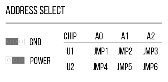
Since there are two chips, each one has to have a unique address. The address is tied to A0, A1, A2 on each chip’s gpio and can be set by setting combinations of GND and POWER.
You can identify each MCP23017 chip by their labels (U1 and U2) and you can set each address manually via jumpers beneath each chip.
For more documentation on MCP23017, see the datasheet: http://ww1.microchip.com/downloads/en/devicedoc/20001952c.pdf
The CD74HC4067 (U3) chip is a switch that internally routes a common pin to 16 channel pins. It works with both digital and analog signals and the connections function in either direction. To control it, we use 4 digital outputs from the MCP23017 (U2) chip to the CD74HC4067 chip’s address select pins (S0-S3) and the Arduino’s A3 pin as a common input. This allows you to connect up to 16 sensors using only 5 pins. You can then use the binary address of the channel you want to sense input from. The Port Extender board labels the 16 channels as its Satellite Analog pins 0 – 15.
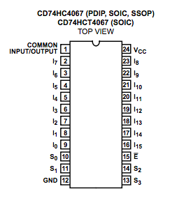
For more documentation on CD74HC4067, see the datasheet: http://www.ti.com/lit/ds/symlink/cd74hc4067.pdf
The CD74HC4051 (U4) chip is a switch that internally routes a common pin to 8 channel pins. To control it, we use 3 digital outputs from the MCP23017 (U2) chip to the CD74HC4067 chip’s address select pins (S0-S2) and the Arduino’s D5~ pin as a common output. This allows you to connect up to 8 PWM outputs using only 4 pins. You can then use the binary address of the channel you want to control as output. The Port Extender board labels the 8 channels as its Satellite PWM pins 0 – 7.
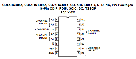
For more documentation on CD74HC4051, see the datasheet: http://www.ti.com/lit/ds/symlink/cd74hc4051.pdf
Along with Arduino’s I2C pins (A4, A5), an Analog pin (A3), and a PWM pin (D5~), the chips used on this board extends the number of digital, analog, and PWM pins to be used with the Museduino system.
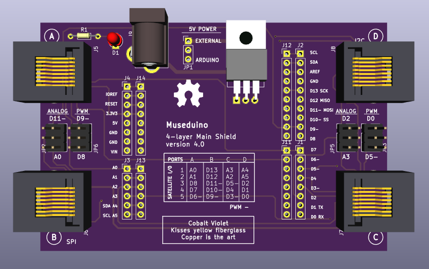
Use the Analog and PWM jumpers on the Museduino main shield to ensure that Port D has access to A3 and D5~.
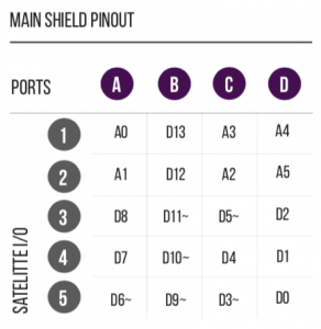
Review the chart below to see which additional pins are routed to the Port Extender Boards rj45 ports.
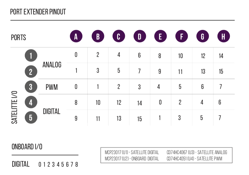
MCP23017 (U1) digital I/O are labeled as Satellite Digital. CD74HC4067 (U3) channels are labeled as Satellite Analog. CD74HC4051 (U4) channels are labeled as Satellite PWM. CD74HC4067 and CD74HC4051 use up 7 digital pins from MCP23017 (U2). The remaining 9 pins are labeled as Onboard Digital.
All Satellite I/O can be accessed via smorgasboard and external power satellite boards. Onboard I/O will require header/wire connections to the pins on the Port Extender Board.
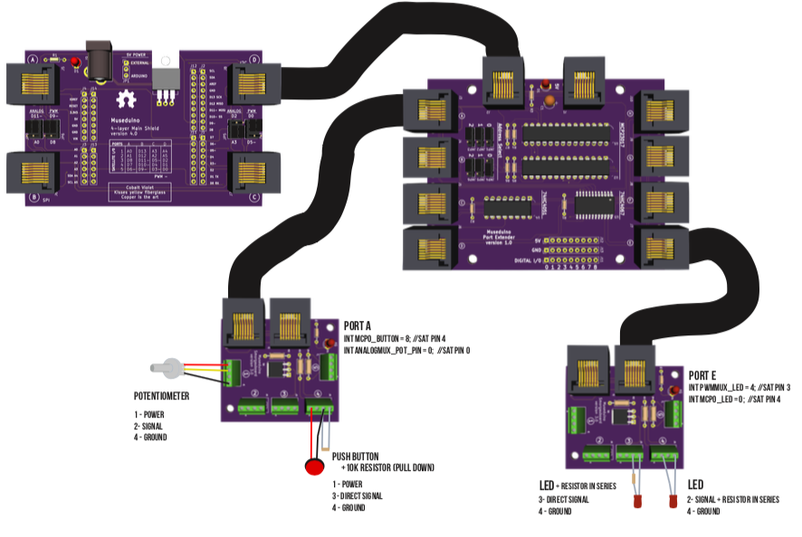
For this tutorial, you will need to use the Port Extender “Address Select” jumpers to set MCP23017 (U1) to address 000 (jmp4 – POWER, jmp5 – GND, jmp6 – GND) and MCP23017 (U2) to address 001 (jmp4 – POWER, jmp5 – GND, jmp6 – GND).
You will also need the following components: Potentiometer, Push Button, 2 Leds, 2 resistors (10k and 220 ohm).
Follow the wiring diagram below:
Currently, we are leveraging the existing Adafruit MCP23017 library to use the MCP23017 chips. To use the CD74HC4067 and CD74HC4051 chips, we use truth tables to set/get the binary address of the channels. Learn more about truth tables and multiplexers here.
For this tutorial, we’ve separated the bulk of the setup required for the Port Extender Board to a header file. Review the code/comments in Museduino_PortExtender.h and Museduino_PortExtender_Tutorial.ino before uploading to your board. You can also download the code from Github.
Museduino_PortExtender.h
#include "Wire.h"
#include "Adafruit_MCP23017.h" // MCP23017 I/O expander Library

Adafruit_MCP23017 mcp0; //U1 on Port Extender board
Adafruit_MCP23017 mcp1; //U2 on Port Extender board

///////////////////////////////////////
// ANALOG MUX - CD74HC4067
// U3 on Port Extender board
// 16 analog input pins - see analog_mux_channel below and chart on PCB
//

//Requires 4 mcp1 library pins and common input from Arduino - see Analog jumpers on Museduino main shield
int analog_s0 = 9;
int analog_s1 = 10;
int analog_s2 = 11;
int analog_s3 = 12;
int analog_common_input = A3; // analog mux common input from arduino
int analog_controlPin[] = {analog_s0, analog_s1, analog_s2, analog_s3};

//analog mux channels for additional analog pins 0-15
int analog_mux_channel[16][4]={
// s0,s1,s2,s3  channel
  {0,0,0,0}, // 0
  {1,0,0,0}, // 1
  {0,1,0,0}, // 2
  {1,1,0,0}, // 3
  {0,0,1,0}, // 4
  {1,0,1,0}, // 5
  {0,1,1,0}, // 6
  {1,1,1,0}, // 7
  {0,0,0,1}, // 8
  {1,0,0,1}, // 9
  {0,1,0,1}, // 10
  {1,1,0,1}, // 11
  {0,0,1,1}, // 12
  {1,0,1,1}, // 13
  {0,1,1,1}, // 14
  {1,1,1,1}  // 15
};

///////////////////////////////////////
// PWM MUX - CD74HC4051E
// U4 on Port Extender board
// 8 pwm output pins - see pwm_mux_channel below and chart on PCB

//Requires 3 mcp1 library pins for and common output from Arduino - see PWM jumpers on Museduino main shield
int pwm_s0 = 13;
int pwm_s1 = 14;
int pwm_s2 = 15;
int pwm_common_output = 5; // mux common output from Arduino
int pwm_controlPin[] = {pwm_s0, pwm_s1, pwm_s2};

//pwm mux channels for additional pwm pins 0-7
int pwm_mux_channel[8][3]={
// s0,s1,s2,s3  channel
  {0,0,0}, // 0
  {1,0,0}, // 1
  {0,1,0}, // 2
  {1,1,0}, // 3
  {0,0,1}, // 4
  {1,0,1}, // 5
  {0,1,1}, // 6
  {1,1,1}, // 7
};

void portextender_setup() {

  //MCP0 - see MCP23017 datasheet and library for address selection
  //default is 0
  mcp0.begin(0); // Address 000 (jmp1 - GND, jmp2 - GND, jmp3 - GND)

  //MCP1
  mcp1.begin(1); //Address 001 (jmp4 - POWER, jmp5 - GND, jmp6 - GND)

  //Analog Mux INPUT control pins from MCP1
  for(int i = 0; i < 4; i ++){
    mcp1.pinMode(analog_controlPin[i], OUTPUT);
    mcp1.pullUp(analog_controlPin[i], HIGH);
    mcp1.digitalWrite(analog_controlPin[i], LOW);
  }
  pinMode(analog_common_input, INPUT);

  //PWM Mux OUTPUT control pins from MCP1
  for(int i = 0; i < 3; i ++){
    mcp1.pinMode(pwm_controlPin[i], OUTPUT);
    mcp1.pullUp(pwm_controlPin[i], HIGH);
    mcp1.digitalWrite(pwm_controlPin[i], LOW);
  }
  pinMode(pwm_common_output, OUTPUT);

}

//ANALOG MUX - read function for Analog Input
int readAnalogMux(int chan){

  Serial.print("analog chan: ");

 //loop through the 4 sig pins control pins
  for(int i = 0; i < 4; i ++){
    Serial.print(analog_mux_channel[chan][i]);
    mcp1.digitalWrite(analog_controlPin[i], analog_mux_channel[chan][i]);
  }
  Serial.println();

  //read the value
  int val = analogRead(analog_common_input); //return the value
  return val;

 }

 //PWM MUX - write function for PWM Output
int writeAnalogPwmMux(int chan, int value){

    Serial.print("pwm chan: ");

    //loop through the 3 sig control pins
    for(int i = 0; i < 3; i ++){
      Serial.print(pwm_mux_channel[chan][i]);
      mcp1.digitalWrite(pwm_controlPin[i], pwm_mux_channel[chan][i]);
    }
    Serial.println();

    Serial.print("pwm mux value: ");
    Serial.println(value);

    //write the value
    analogWrite(pwm_common_output,value); //return the value

 }

//PWM MUX - write function for Digital Output
int writeDigitalPwmMux(int chan, int value){

    Serial.print("pwm chan: ");

    //loop through the 3 sig control pins
    for(int i = 0; i < 3; i ++){
      Serial.print(pwm_mux_channel[chan][i]);
      mcp1.digitalWrite(pwm_controlPin[i], pwm_mux_channel[chan][i]);
    }
    Serial.println();

    Serial.print("pwm mux value: ");
    Serial.println(value);

    //write the value
    digitalWrite(pwm_common_output,value); //return the value

 }
Museduino_PortExtender_Tutorial.ino
#include "Museduino_PortExtender.h"
int mcp0_button = 8; // Port A, Sat Pin 4
int mcp0_button_state = 0;

int mcp0_LED = 0; // Port E, Sat Pin 4

// Connect a potentiometer to analog mux pin 0
int analogMux_pot_pin = 0; //Port A, Sat Pin 0
int analogMux_pot_value = 0;
// Connect an led to pwm mux pin 4
int pwmMux_LED = 4; //Port E, Sat Pin 3
void setup() {

  //setup all chips on the Port Extender:
  portextender_setup();

  //PWM Mux Pins are set as Output
  //Analog Mux Pins are set to Input
  //Use Adafruit MCP23017 library define Digital Pins on mcp0 and mcp1
  //mcp0 should be used for Satellite Digital I/O
  //mcp1 should be used for Onboard Digital I/O

  mcp0.pinMode(mcp0_button, INPUT);
  mcp0.pinMode(mcp0_LED, OUTPUT);


}

void loop() {
  mcp0_button_state = mcp0.digitalRead(mcp0_button); //read digital input
  Serial.print("mcp0 button state: ");
  Serial.println(mcp0_button_state);

  //write digital input
  if (mcp0_button_state) {
    mcp0.digitalWrite(mcp0_LED,HIGH);
  } else {
    mcp0.digitalWrite(mcp0_LED,LOW);
  }

  analogMux_pot_value = readAnalogMux(analogMux_pot_pin); //read analog

  analogMux_pot_value = map(analogMux_pot_value, 0, 1023, 0, 255); //map 0-255
  Serial.print("analog mux value: ");
  Serial.println(analogMux_pot_value);

  writePwmMux(pwmMux_LED, analogMux_pot_value); //analogWrite to pwm mux
}
Migrating to Circuit Python?
In order to evenly distribute the Arduino Uno’s pins to each Port (rj-45), we used A4 and A5 instead of the dedicated i2c pinout (SCL, SDA). Although A4 and A5 are technically tied to SCL and SDA on an Arduino Uno, circuit python boards with an uno footprint do not always use A4 and A5 as i2c pins. Make sure to check your pinout/datasheets.
This tutorial will teach you how to setup a DC motor with the Satellite boards built-in Mosfet and how to control the motor speed using Analog input.
Arduino
A/B USB connectors
Museduino Shield
2 Satellite boards
CAT5 cable
DC Motor
10k Potentiometer
screw driver
First, complete the instructions for the DC Motor tutorial.
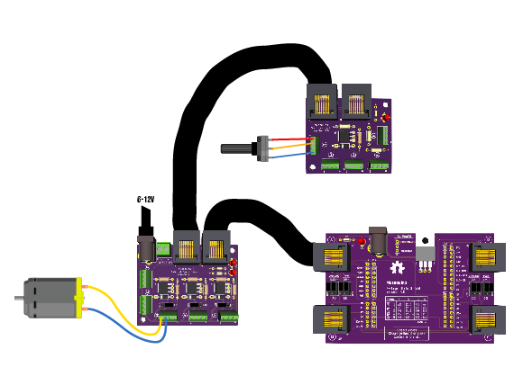
Now let’s add potentiometer on Arduino Analog Pin A0 using a second Satellite board. Use the Analog Select chart to configure the jumper shunts in the correct Down position.

Once you’ve configured the jumpers, we need to wire the potentiometer to the following screw terminal configuration:
1 – Power
2 – Direct Signal
4 – Ground
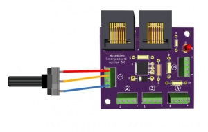
Each Satellite is designed with 2 RJ-45 connectors allowing multiple Satellite boards to be daisy chained with distance between sensors/actuators.
Copy code below or download from Github. Upload the sketch.
/*
  Museduino | DC Motor Tutorial
  Control the speed of a DC moto with a potentiometer
*/

//satellite Pin 1 on Port A
int s1A = A0;

//satellite Pin 3 on Port A
int s3A = 9; //default arduino pin is D8, use Analog Select to swap with D9~

int motorSpeed = 0; //motor speed value

// the setup routine runs once when you press reset:
void setup() {

  Serial.begin(9600);

  // initialize potentiometer as input and the motor pin as an output.
  pinMode(s1A, INPUT);
  pinMode(s3A, OUTPUT);

}

// the loop routine runs over and over again forever:
void loop() {

  //read value from potentiometer
  motorSpeed = analogRead(s1A);

  //map value from 0 (off) to 255 (on)
  motorSpeed = map(motorSpeed, 1023, 0, 0, 255);

  Serial.println(motorSpeed);

  //if motorSpeed > 0, set the speed
  if(motorSpeed > 0) {
    analogWrite(s3A, motorSpeed);
  } else {
    //stop the motor
    digitalWrite(s3A, LOW);
  }


}
Need More Satellite I/O? Checkout the new Port Extender Satellite board.
This tutorial will teach you how to setup a DC motor with the Satellite boards built-in Mosfet and how to control the motor speed using Serial input.
Arduino
A/B USB connectors
Museduino Shield
Satellite board
CAT5 cable
DC Motor
screw driver
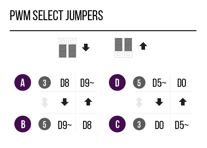
For this tutorial we are going to use Arduino pin D9~.

D9~ pin can be accessed on either Satellite I/O 3 on Port A or Satellite I/O 5 on Port B. Place PWM Select jumpers in the default Up position so that D9~ is available on Port A.
Before we get started, take a look at the Pin Configuration Chart.
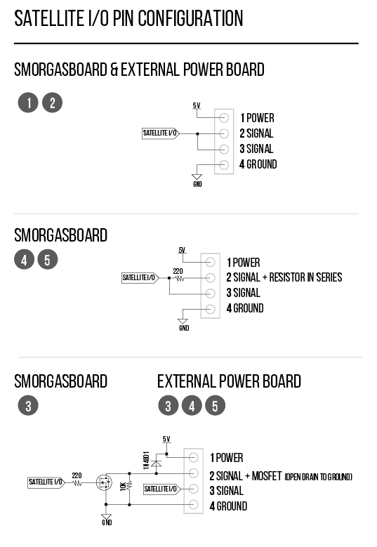
Both the Smorgasboard and External Power boards have a built-in Mosfet, which is a type of transistor meant for actuators that require more power than an Arduino digital output can handle directly.
The Arduino can only provide 40mA at 5V on its digital pins. Most motors require more current and/or voltage to operate. A transistor can act as a digital switch, enabling the Arduino to control loads with higher electrical requirements.
With a mosfet, you have an “in” called the Source, an “out” called the Drain, and a “control” called the Gate. When you send a HIGH signal to the gate (Signal pin), the transistor switches and allows current or voltage to flow from the source (in) to the drain (out). Ground is connected to the transistor’s drain. A pull-down resistor holds the gate low when the signal pin is LOW.
Learn more about transistors and mosfets here:
https://learn.adafruit.com/transistors-101
When working with actuators that have a coil (DC motors, relay, solenoid), it is also important to use a “snubber” or “flyback” Diode, which is a diode used to eliminate negative voltage spikes when power is suddenly reduced or removed.
To prevent damage to the Mosfets on your Satellite boards, the latest versions now include a diode and a pull-down resistor to complete the circuit. For older versions, you must use a diode in parallel with the motor (between screw terminal pins 1 – power and 2- signal) and a 10k pull-down resistor (between screw terminal pins 3 – direct signal and 4 – ground).
Now let’s hook up the motor. DC motors can usually run with either polarity but direction of rotation will be reversed. Connect one wire of your motor to screw terminal pin 1 for power and the other wire to screw terminal pin 2 for Signal with an Open Drain to Ground.
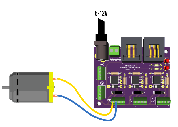
This circuit is okay to use with a 5v hobby motor. For motors requiring 6v or higher, use External Power.
This tutorial uses Pulse-width modulation (PWM) to simulate a variable supply voltage. The voltage supplied to a DC motor controls its speed.
Copy code below or download from Github.
Upload the sketch and open the serial monitor to set a motor speed value of 0 to 255.
/*
  Museduino | DC Motor Tutorial
  Set the speed of a DC motor using Serial
*/

//satellite Pin 3 on Port A
int s3A = 9; //default arduino pin is D8, use PWM Select to swap with D9~


// the setup routine runs once:
void setup() {
  // initialize the serial communication
  Serial.begin(9600);

  // initialize motor pin as an output
  pinMode(s3A, OUTPUT);

  Serial.println("Speed 0 to 255");


}

// the loop routine runs over and over again forever:
void loop() {

    int speed; //motor speed value must be 0 to 255

    // check if data has been sent over serial
    if (Serial.available()) {
      // parse the most recent int (0 to 255):
      speed = Serial.parseInt();

      if (speed >= 0 && speed <= 255) {
         //set the speed of the motor
         analogWrite(s3A, speed);
      }

    }

}
Want to control the speed of the motor with an analog input?
This tutorial will teach you how to use the External Power Satellite board with a NeoPixel RGB LED Strip.
Arduino
A/B USB cable
Museduino Shield
Museduino External Power board
CAT5 cable
NeoPixel RGB LED Strip
5v 2 amp Switching Power Supply
300-500 ohm resistor
1000µF, 6.3V or higher capacitor
screwdriver
For detailed information about Neopixels, please review the Adafruit NeoPixel Uberguide. For this tutorial, we use a 1 meter NeoPixel LED Strip (60pixel/meter). The Neopixel Uberguide suggests a power supply with a minimum of 1.2 amps. We recommend using a 5V 2amp Switching Power Supply.
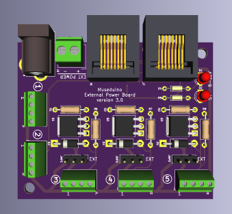
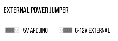
Take a look at the External Power satellite board. Notice that the board is equipped with a DC barrel jack and a 2pin screw terminal for power and ground. Either connection can be used as an external power source. When an external power source is connected, the LED indicating 6-12V will be on. The board also contains External Power Jumpers on Satellite I/O pins 3, 4, 5 which allow you to switch from 5V to the 6-12V supply.
To connect a NeoPixel Strip, we are going to use Arduino Digital Pin 6 (Satellite Pin 5 on Port A).
Locate Satellite I/O pin 5 on the External Power board. Based on the Satellite pin configuration, you will use screw terminal block pins 1 (power), 3 (direct signal), and 4 (ground).
The Neopixel Strip has four colored wires; red (power), white (signal/data), and two black (ground). We will also use a 470 ohm resistor between the microcontroller signal pin and the Neopixel data input pin to help prevent spikes on the data line that can damage the first pixel. Feel free to use a breadboard for this exercise or solder the resistor in series with the signal/data wire.
It is best practice to avoid connecting NeoPixels to a live circuit. Always connect ground first, then +5V, then data. Disconnect in the reverse order. A small screwdriver is needed to tighten/loosen the screw terminals.
Connect both black Neopixel wires to screw terminal pin 4 (ground), the red Neopixel wire to screw terminal pin 1 (power), and the white Neopixel wire to screw terminal pin 3 (direct signal).
Before connecting NeoPixels to the power source, use the 2 pin screw terminal to connect a capacitor across the + and – terminals. This will help buffer sudden changes in the current drawn by the strip.
Next, find the External Power jumper directly above satellite pin 5. Move the jumper shunt to the right to switch to external power.
Now plugin the 5v 2amp Switching Power Supply to the DC barrel jack.
Via CAT5 cable, connect the External Power satellite power board to Port A. Then connect your Arduino via usb to upload the program to control the NeoPixel strip.
Download the Adafruit_NeoPixel library. For this tutorial, upload the strand test sketch to your Arduino.
Want to use DC motors with Museduino? Go to the next tutorial.
This tutorial will teach you how to use Analog Select Jumpers with a potentiometer and servo motor.
Arduino
A/B USB cable
Museduino Shield
2 Museduino Satellite Boards
CAT5 cable
servo motor
screw driver
prototyping wire
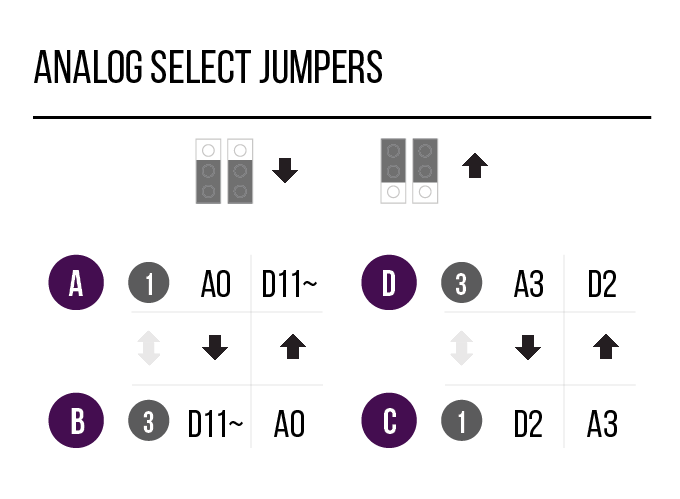
Before we get started, let’s learn about the Analog Select feature on the Main Shield. Locate the header pins (2×3 block) labeled “ANALOG” between the RJ-45 connecters.
The Analog Select feature on the main shield is designed to swap pins between two ports. The Analog Select switch on the left of the main shield can be used to swap Satellite I/O pin 1 on Port A with Satellite I/O pin 3 on B. The Analog Select switch on the right of the main shield can be used to swap Satellite Pin 1 on Port C with Satellite I/O pin 3 on D.
In order to use the switches, you must use the jumper shunts provided. There are two jumper shunts for each Analog Select switch (2×3 block) and they both must be placed in an “Up” or “Down” position.
Below is a chart to assist with the proper jumper configuration:
Now that you have learned about the Analog Select feature, let’s use a potentiometer on Arduino Pin A0.
The chart shows that Arduino Pin A0 is available from Satellite I/O pin 1 on Port A (default UP position). Since the Analog jumpers can be used to swap Satellite I/O pin 3 on Port C with Satellite I/O pin 5 on D, this means we can swap A0 and D11~. Place the jumper shunts in a “Down” position to make A0 available from Satellite Pin 1 on Port A.
Satellite I/O pins 1 and 2 are intended for use with Analog Inputs. Connect a potentiometer to Satellite I/O pin 1.
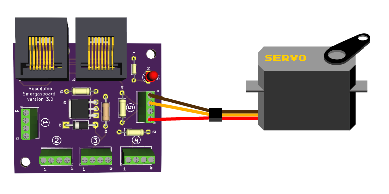
We will need to use Power (screw terminal 1), Signal (screw terminal 2 or 3), Ground (screw terminal 4) on either a Smorgasboard or External Power Board. Connect the Satellite board to Port A.

Next, connect a servo motor to Arduino pin D9~ ( Satellite I/O pin 5 on Port B). We will need to use Power (screw terminal 1), Signal (screw terminal 3), Ground (screw terminal 4) on either a Smorgasboard or External Power Board. Connect the Satellite board to Port B.
Copy code below or download from Github.
Upload the sketch.
/*
Museduino | Servo Motors (PWM Select) Tutorial
Control servo position using a potentiometer (variable resistor)
*/

#include "servo.h"

Servo servo;  // create servo object to control a servo

int s1A = A0;  // analog pin used to connect the potentiometer - Satellite Pin 1 on Port A

int s5B = 9; // digital/pwm pin used to connect the servo - Satellite I/O Pin 5 on Port B

int val; // variable to read the value from the analog pin

void setup()
{
  servo.attach(s5B);  // attaches the servo on D9~ to the servo object (satellite pin 5 on B)
}

void loop()
{
  val = analogRead(s1A);            // reads the value of the potentiometer (value between 0 and 1023)
  val = map(val, 0, 1023, 0, 180);  // remap to use it with the servo (value between 0 and 180)
  servo.write(val);                 // sets the servo position according to the scaled value
  delay(15);                        // waits for the servo to get there
}
Want to use Neopixels with Museduino?