Overview
This tutorial will teach you how to use Analog Select Jumpers with a potentiometer and servo motor.
Components
Arduino
A/B USB cable
Museduino Shield
2 Museduino Satellite Boards
CAT5 cable
servo motor
screw driver
prototyping wire
Setup
Before we get started, let’s learn about the Analog Select feature on the Main Shield. Locate the header pins (2×3 block) labeled “ANALOG” between the RJ-45 connecters.
The Analog Select feature on the main shield is designed to swap pins between two ports. The Analog Select switch on the left of the main shield can be used to swap Satellite I/O pin 1 on Port A with Satellite I/O pin 3 on B. The Analog Select switch on the right of the main shield can be used to swap Satellite Pin 1 on Port C with Satellite I/O pin 3 on D.
In order to use the switches, you must use the jumper shunts provided. There are two jumper shunts for each Analog Select switch (2×3 block) and they both must be placed in an “Up” or “Down” position.
Below is a chart to assist with the proper jumper configuration:
Now that you have learned about the Analog Select feature, let’s use a potentiometer on Arduino Pin A0.
The chart shows that Arduino Pin A0 is available from Satellite I/O pin 1 on Port A (default UP position). Since the Analog jumpers can be used to swap Satellite I/O pin 3 on Port C with Satellite I/O pin 5 on D, this means we can swap A0 and D11~. Place the jumper shunts in a “Down” position to make A0 available from Satellite Pin 1 on Port A.
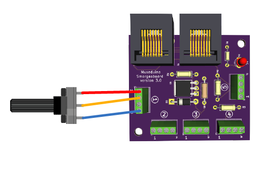
Satellite I/O pins 1 and 2 are intended for use with Analog Inputs. Connect a potentiometer to Satellite I/O pin 1.
We will need to use Power (screw terminal 1), Signal (screw terminal 2 or 3), Ground (screw terminal 4) on either a Smorgasboard or External Power Board. Connect the Satellite board to Port A.
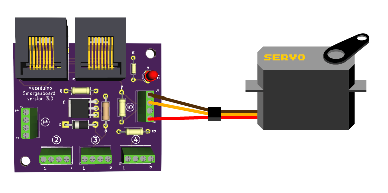
Next, connect a servo motor to Arduino pin D9~ ( Satellite I/O pin 5 on Port B). We will need to use Power (screw terminal 1), Signal (screw terminal 3), Ground (screw terminal 4) on either a Smorgasboard or External Power Board. Connect the Satellite board to Port B.
Code
Copy code below or download from Github.
Upload the sketch.
/*
Museduino | Servo Motors (PWM Select) Tutorial
Control servo position using a potentiometer (variable resistor)
*/

#include "servo.h"

Servo servo;  // create servo object to control a servo

int s1A = A0;  // analog pin used to connect the potentiometer - Satellite Pin 1 on Port A

int s5B = 9; // digital/pwm pin used to connect the servo - Satellite I/O Pin 5 on Port B

int val; // variable to read the value from the analog pin

void setup()
{
  servo.attach(s5B);  // attaches the servo on D9~ to the servo object (satellite pin 5 on B)
}

void loop()
{
  val = analogRead(s1A);            // reads the value of the potentiometer (value between 0 and 1023)
  val = map(val, 0, 1023, 0, 180);  // remap to use it with the servo (value between 0 and 180)
  servo.write(val);                 // sets the servo position according to the scaled value
  delay(15);                        // waits for the servo to get there
}
Want to use Neopixels with Museduino?