Overview
This tutorial will teach you how to use the External Power Satellite board with a NeoPixel RGB LED Strip.
Components
Arduino
A/B USB cable
Museduino Shield
Museduino External Power board
CAT5 cable
NeoPixel RGB LED Strip
5v 2 amp Switching Power Supply
300-500 ohm resistor
1000µF, 6.3V or higher capacitor
screwdriver
Setup
For detailed information about Neopixels, please review the Adafruit NeoPixel Uberguide. For this tutorial, we use a 1 meter NeoPixel LED Strip (60pixel/meter). The Neopixel Uberguide suggests a power supply with a minimum of 1.2 amps. We recommend using a 5V 2amp Switching Power Supply.
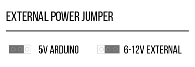
Take a look at the External Power satellite board. Notice that the board is equipped with a DC barrel jack and a 2pin screw terminal for power and ground. Either connection can be used as an external power source. When an external power source is connected, the LED indicating 6-12V will be on. The board also contains External Power Jumpers on Satellite I/O pins 3, 4, 5 which allow you to switch from 5V to the 6-12V supply.
To connect a NeoPixel Strip, we are going to use Arduino Digital Pin 6 (Satellite Pin 5 on Port A).
Locate Satellite I/O pin 5 on the External Power board. Based on the Satellite pin configuration, you will use screw terminal block pins 1 (power), 3 (direct signal), and 4 (ground).
The Neopixel Strip has four colored wires; red (power), white (signal/data), and two black (ground). We will also use a 470 ohm resistor between the microcontroller signal pin and the Neopixel data input pin to help prevent spikes on the data line that can damage the first pixel. Feel free to use a breadboard for this exercise or solder the resistor in series with the signal/data wire.
It is best practice to avoid connecting NeoPixels to a live circuit. Always connect ground first, then +5V, then data. Disconnect in the reverse order. A small screwdriver is needed to tighten/loosen the screw terminals.
Connect both black Neopixel wires to screw terminal pin 4 (ground), the red Neopixel wire to screw terminal pin 1 (power), and the white Neopixel wire to screw terminal pin 3 (direct signal).
Before connecting NeoPixels to the power source, use the 2 pin screw terminal to connect a capacitor across the + and – terminals. This will help buffer sudden changes in the current drawn by the strip.
Next, find the External Power jumper directly above satellite pin 5. Move the jumper shunt to the right to switch to external power.
Now plugin the 5v 2amp Switching Power Supply to the DC barrel jack.
Via CAT5 cable, connect the External Power satellite power board to Port A. Then connect your Arduino via usb to upload the program to control the NeoPixel strip.
Code
Download the Adafruit_NeoPixel library. For this tutorial, upload the strand test sketch to your Arduino.
Want to use DC motors with Museduino? Go to the next tutorial.