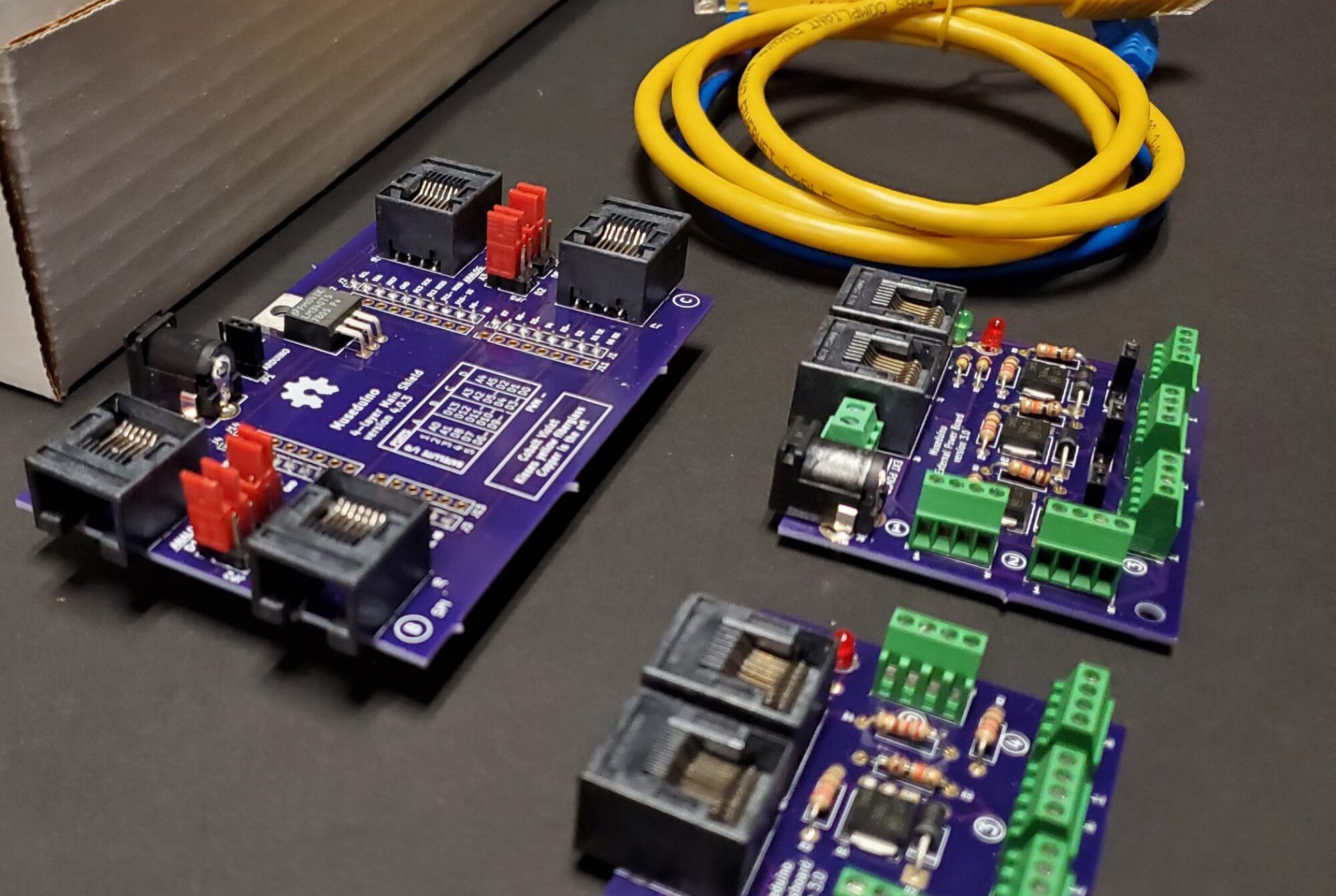
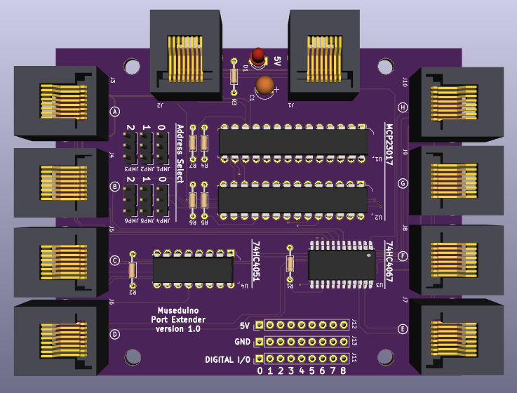
The Port Extender board was designed for use with the dedicated I2C port, Port D on the Main Shield and intended for projects that need to control more input and output devices. The Port Extender is equipped with two MCP23017 i2c 16-bit i/o digital port expanders, a CD74HC4067 16-channel multiplexer, and a CD74HC4051 8-channel multiplexer.
I2C Protocol
I2C, or inter-integrated circuit, is a two wire serial protocol for sending and receiving data. The two wires are Serial Clock (or SCL) and Serial Data (or SDA) and referred to as the I2C bus. The SCL line is the clock signal which synchronize the data transfer between the devices on the I2C bus and it’s generated by the master device. The other line is the SDA line which carries the data. The Arduino Uno has dedicated SCL and SDA pins, but both are tied to pins A5 (SCL) and A4 (SDA).
Multiple I2C devices can be connected on the I2C bus. This means that you connect many I2C breakout boards and sensors using just the SCL and SDA pins. As a result of using 7-bit addresses the I2C protocol is limited to 127 unique devices.
Addresses on I2C bus cannot be the same. This means you cannot use multiple of the same I2C breakout board or sensor if they have fixed addresses. Some I2C devices allow you change the address in software or hardware via jumpers.
Learn more about about I2C here: https://learn.adafruit.com/i2c-addresses
MCP23017
The Port Extender board has two MCP23017 chips that use the I2C protocol. Each MCP23017 chip provides an 16 additional digital i/o pins that are read/written to via the I2C pins.
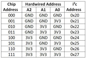
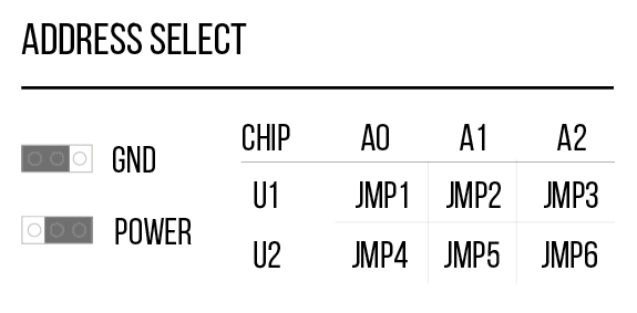
Since there are two chips, each one has to have a unique address. The address is tied to A0, A1, A2 on each chip’s gpio and can be set by setting combinations of GND and POWER.
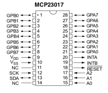
You can identify each MCP23017 chip by their labels (U1 and U2) and you can set each address manually via jumpers beneath each chip.
For more documentation on MCP23017, see the datasheet: http://ww1.microchip.com/downloads/en/devicedoc/20001952c.pdf
CD74HC4067
The CD74HC4067 (U3) chip is a switch that internally routes a common pin to 16 channel pins. It works with both digital and analog signals and the connections function in either direction. To control it, we use 4 digital outputs from the MCP23017 (U2) chip to the CD74HC4067 chip’s address select pins (S0-S3) and the Arduino’s A3 pin as a common input. This allows you to connect up to 16 sensors using only 5 pins. You can then use the binary address of the channel you want to sense input from. The Port Extender board labels the 16 channels as its Satellite Analog pins 0 – 15.
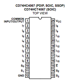
For more documentation on CD74HC4067, see the datasheet: http://www.ti.com/lit/ds/symlink/cd74hc4067.pdf
CD74HC4051
The CD74HC4051 (U4) chip is a switch that internally routes a common pin to 8 channel pins. To control it, we use 3 digital outputs from the MCP23017 (U2) chip to the CD74HC4067 chip’s address select pins (S0-S2) and the Arduino’s D5~ pin as a common output. This allows you to connect up to 8 PWM outputs using only 4 pins. You can then use the binary address of the channel you want to control as output. The Port Extender board labels the 8 channels as its Satellite PWM pins 0 – 7.
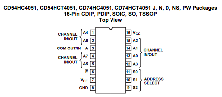
For more documentation on CD74HC4051, see the datasheet: http://www.ti.com/lit/ds/symlink/cd74hc4051.pdf
SETUP
Along with Arduino’s I2C pins (A4, A5), an Analog pin (A3), and a PWM pin (D5~), the chips used on this board extends the number of digital, analog, and PWM pins to be used with the Museduino system.
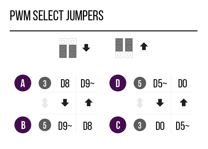
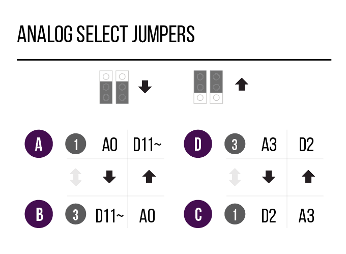
Use the Analog and PWM jumpers on the Museduino main shield to ensure that Port D has access to A3 and D5~.
Review the chart below to see which additional pins are routed to the Port Extender Boards rj45 ports.
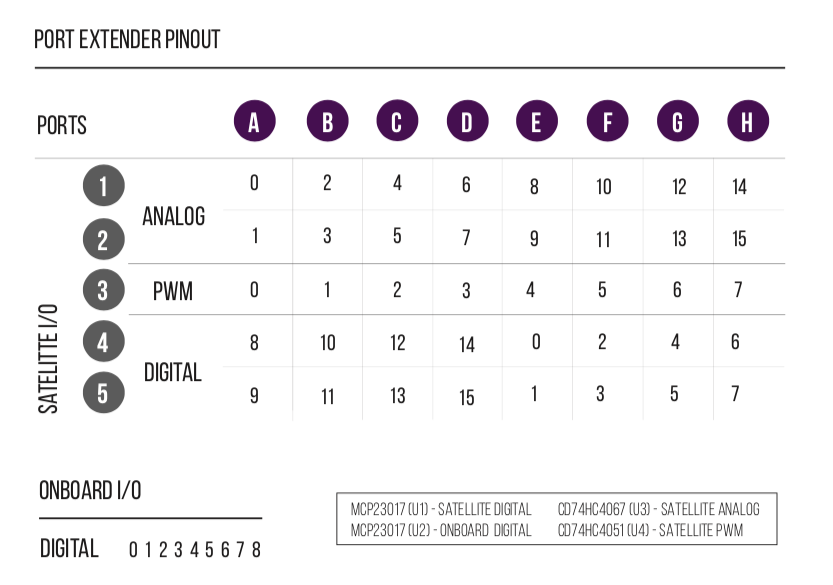
MCP23017 (U1) digital I/O are labeled as Satellite Digital. CD74HC4067 (U3) channels are labeled as Satellite Analog. CD74HC4051 (U4) channels are labeled as Satellite PWM. CD74HC4067 and CD74HC4051 use up 7 digital pins from MCP23017 (U2). The remaining 9 pins are labeled as Onboard Digital.
All Satellite I/O can be accessed via smorgasboard and external power satellite boards. Onboard I/O will require header/wire connections to the pins on the Port Extender Board.
For this tutorial, you will need to use the Port Extender “Address Select” jumpers to set MCP23017 (U1) to address 000 (jmp4 – POWER, jmp5 – GND, jmp6 – GND) and MCP23017 (U2) to address 001 (jmp4 – POWER, jmp5 – GND, jmp6 – GND).
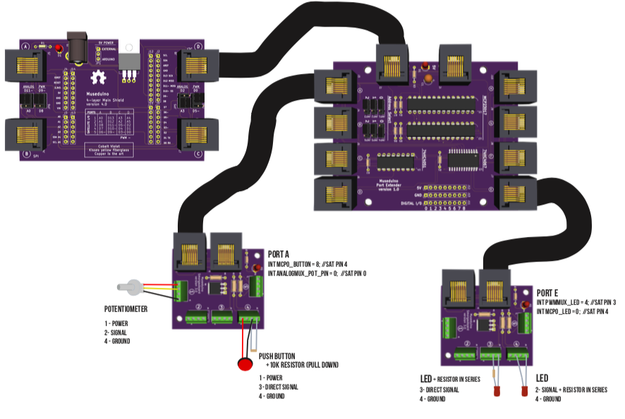
You will also need the following components: Potentiometer, Push Button, 2 Leds, 2 resistors (10k and 220 ohm).
Follow the wiring diagram below:
Code
Currently, we are leveraging the existing Adafruit MCP23017 library to use the MCP23017 chips. To use the CD74HC4067 and CD74HC4051 chips, we use truth tables to set/get the binary address of the channels. Learn more about truth tables and multiplexers here.
For this tutorial, we’ve separated the bulk of the setup required for the Port Extender Board to a header file. Review the code/comments in Museduino_PortExtender.h and Museduino_PortExtender_Tutorial.ino before uploading to your board. You can also download the code from Github.
Museduino_PortExtender.h
#include "Wire.h"
#include "Adafruit_MCP23017.h" // MCP23017 I/O expander Library

Adafruit_MCP23017 mcp0; //U1 on Port Extender board
Adafruit_MCP23017 mcp1; //U2 on Port Extender board

///////////////////////////////////////
// ANALOG MUX - CD74HC4067
// U3 on Port Extender board
// 16 analog input pins - see analog_mux_channel below and chart on PCB
//

//Requires 4 mcp1 library pins and common input from Arduino - see Analog jumpers on Museduino main shield
int analog_s0 = 9;
int analog_s1 = 10;
int analog_s2 = 11;
int analog_s3 = 12;
int analog_common_input = A3; // analog mux common input from arduino
int analog_controlPin[] = {analog_s0, analog_s1, analog_s2, analog_s3};

//analog mux channels for additional analog pins 0-15
int analog_mux_channel[16][4]={
// s0,s1,s2,s3  channel
  {0,0,0,0}, // 0
  {1,0,0,0}, // 1
  {0,1,0,0}, // 2
  {1,1,0,0}, // 3
  {0,0,1,0}, // 4
  {1,0,1,0}, // 5
  {0,1,1,0}, // 6
  {1,1,1,0}, // 7
  {0,0,0,1}, // 8
  {1,0,0,1}, // 9
  {0,1,0,1}, // 10
  {1,1,0,1}, // 11
  {0,0,1,1}, // 12
  {1,0,1,1}, // 13
  {0,1,1,1}, // 14
  {1,1,1,1}  // 15
};

///////////////////////////////////////
// PWM MUX - CD74HC4051E
// U4 on Port Extender board
// 8 pwm output pins - see pwm_mux_channel below and chart on PCB

//Requires 3 mcp1 library pins for and common output from Arduino - see PWM jumpers on Museduino main shield
int pwm_s0 = 13;
int pwm_s1 = 14;
int pwm_s2 = 15;
int pwm_common_output = 5; // mux common output from Arduino
int pwm_controlPin[] = {pwm_s0, pwm_s1, pwm_s2};

//pwm mux channels for additional pwm pins 0-7
int pwm_mux_channel[8][3]={
// s0,s1,s2,s3  channel
  {0,0,0}, // 0
  {1,0,0}, // 1
  {0,1,0}, // 2
  {1,1,0}, // 3
  {0,0,1}, // 4
  {1,0,1}, // 5
  {0,1,1}, // 6
  {1,1,1}, // 7
};

void portextender_setup() {

  //MCP0 - see MCP23017 datasheet and library for address selection
  //default is 0
  mcp0.begin(0); // Address 000 (jmp1 - GND, jmp2 - GND, jmp3 - GND)

  //MCP1
  mcp1.begin(1); //Address 001 (jmp4 - POWER, jmp5 - GND, jmp6 - GND)

  //Analog Mux INPUT control pins from MCP1
  for(int i = 0; i < 4; i ++){
    mcp1.pinMode(analog_controlPin[i], OUTPUT);
    mcp1.pullUp(analog_controlPin[i], HIGH);
    mcp1.digitalWrite(analog_controlPin[i], LOW);
  }
  pinMode(analog_common_input, INPUT);

  //PWM Mux OUTPUT control pins from MCP1
  for(int i = 0; i < 3; i ++){
    mcp1.pinMode(pwm_controlPin[i], OUTPUT);
    mcp1.pullUp(pwm_controlPin[i], HIGH);
    mcp1.digitalWrite(pwm_controlPin[i], LOW);
  }
  pinMode(pwm_common_output, OUTPUT);

}

//ANALOG MUX - read function for Analog Input
int readAnalogMux(int chan){

  Serial.print("analog chan: ");

 //loop through the 4 sig pins control pins
  for(int i = 0; i < 4; i ++){
    Serial.print(analog_mux_channel[chan][i]);
    mcp1.digitalWrite(analog_controlPin[i], analog_mux_channel[chan][i]);
  }
  Serial.println();

  //read the value
  int val = analogRead(analog_common_input); //return the value
  return val;

 }

 //PWM MUX - write function for PWM Output
int writeAnalogPwmMux(int chan, int value){

    Serial.print("pwm chan: ");

    //loop through the 3 sig control pins
    for(int i = 0; i < 3; i ++){
      Serial.print(pwm_mux_channel[chan][i]);
      mcp1.digitalWrite(pwm_controlPin[i], pwm_mux_channel[chan][i]);
    }
    Serial.println();

    Serial.print("pwm mux value: ");
    Serial.println(value);

    //write the value
    analogWrite(pwm_common_output,value); //return the value

 }

//PWM MUX - write function for Digital Output
int writeDigitalPwmMux(int chan, int value){

    Serial.print("pwm chan: ");

    //loop through the 3 sig control pins
    for(int i = 0; i < 3; i ++){
      Serial.print(pwm_mux_channel[chan][i]);
      mcp1.digitalWrite(pwm_controlPin[i], pwm_mux_channel[chan][i]);
    }
    Serial.println();

    Serial.print("pwm mux value: ");
    Serial.println(value);

    //write the value
    digitalWrite(pwm_common_output,value); //return the value

 }
Museduino_PortExtender_Tutorial.ino
#include "Museduino_PortExtender.h"
int mcp0_button = 8; // Port A, Sat Pin 4
int mcp0_button_state = 0;

int mcp0_LED = 0; // Port E, Sat Pin 4

// Connect a potentiometer to analog mux pin 0
int analogMux_pot_pin = 0; //Port A, Sat Pin 0
int analogMux_pot_value = 0;
// Connect an led to pwm mux pin 4
int pwmMux_LED = 4; //Port E, Sat Pin 3
void setup() {

  //setup all chips on the Port Extender:
  portextender_setup();

  //PWM Mux Pins are set as Output
  //Analog Mux Pins are set to Input
  //Use Adafruit MCP23017 library define Digital Pins on mcp0 and mcp1
  //mcp0 should be used for Satellite Digital I/O
  //mcp1 should be used for Onboard Digital I/O

  mcp0.pinMode(mcp0_button, INPUT);
  mcp0.pinMode(mcp0_LED, OUTPUT);


}

void loop() {
  mcp0_button_state = mcp0.digitalRead(mcp0_button); //read digital input
  Serial.print("mcp0 button state: ");
  Serial.println(mcp0_button_state);

  //write digital input
  if (mcp0_button_state) {
    mcp0.digitalWrite(mcp0_LED,HIGH);
  } else {
    mcp0.digitalWrite(mcp0_LED,LOW);
  }

  analogMux_pot_value = readAnalogMux(analogMux_pot_pin); //read analog

  analogMux_pot_value = map(analogMux_pot_value, 0, 1023, 0, 255); //map 0-255
  Serial.print("analog mux value: ");
  Serial.println(analogMux_pot_value);

  writePwmMux(pwmMux_LED, analogMux_pot_value); //analogWrite to pwm mux
}
Migrating to Circuit Python?
In order to evenly distribute the Arduino Uno’s pins to each Port (rj-45), we used A4 and A5 instead of the dedicated i2c pinout (SCL, SDA). Although A4 and A5 are technically tied to SCL and SDA on an Arduino Uno, circuit python boards with an uno footprint do not always use A4 and A5 as i2c pins. Make sure to check your pinout/datasheets.