Overview
This tutorial will teach you how to setup a DC motor with the Satellite boards built-in Mosfet and how to control the motor speed using Serial input.
Components
Arduino
A/B USB connectors
Museduino Shield
Satellite board
CAT5 cable
DC Motor
screw driver
Setup
For this tutorial we are going to use Arduino pin D9~.
D9~ pin can be accessed on either Satellite I/O 3 on Port A or Satellite I/O 5 on Port B. Place PWM Select jumpers in the default Up position so that D9~ is available on Port A.
Before we get started, take a look at the Pin Configuration Chart.
Both the Smorgasboard and External Power boards have a built-in Mosfet, which is a type of transistor meant for actuators that require more power than an Arduino digital output can handle directly.
The Arduino can only provide 40mA at 5V on its digital pins. Most motors require more current and/or voltage to operate. A transistor can act as a digital switch, enabling the Arduino to control loads with higher electrical requirements.
With a mosfet, you have an “in” called the Source, an “out” called the Drain, and a “control” called the Gate. When you send a HIGH signal to the gate (Signal pin), the transistor switches and allows current or voltage to flow from the source (in) to the drain (out). Ground is connected to the transistor’s drain. A pull-down resistor holds the gate low when the signal pin is LOW.
Learn more about transistors and mosfets here:
https://learn.adafruit.com/transistors-101
When working with actuators that have a coil (DC motors, relay, solenoid), it is also important to use a “snubber” or “flyback” Diode, which is a diode used to eliminate negative voltage spikes when power is suddenly reduced or removed.
To prevent damage to the Mosfets on your Satellite boards, the latest versions now include a diode and a pull-down resistor to complete the circuit. For older versions, you must use a diode in parallel with the motor (between screw terminal pins 1 – power and 2- signal) and a 10k pull-down resistor (between screw terminal pins 3 – direct signal and 4 – ground).
Now let’s hook up the motor. DC motors can usually run with either polarity but direction of rotation will be reversed. Connect one wire of your motor to screw terminal pin 1 for power and the other wire to screw terminal pin 2 for Signal with an Open Drain to Ground.
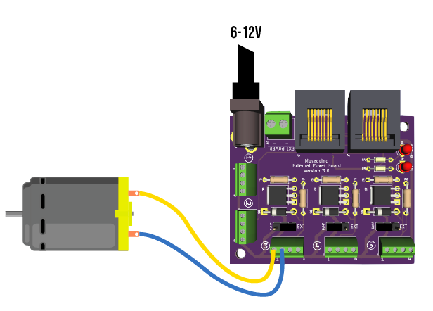
This circuit is okay to use with a 5v hobby motor. For motors requiring 6v or higher, use External Power.
Code
This tutorial uses Pulse-width modulation (PWM) to simulate a variable supply voltage. The voltage supplied to a DC motor controls its speed.
Copy code below or download from Github.
Upload the sketch and open the serial monitor to set a motor speed value of 0 to 255.
/*
  Museduino | DC Motor Tutorial
  Set the speed of a DC motor using Serial
*/

//satellite Pin 3 on Port A
int s3A = 9; //default arduino pin is D8, use PWM Select to swap with D9~


// the setup routine runs once:
void setup() {
  // initialize the serial communication
  Serial.begin(9600);

  // initialize motor pin as an output
  pinMode(s3A, OUTPUT);

  Serial.println("Speed 0 to 255");


}

// the loop routine runs over and over again forever:
void loop() {

    int speed; //motor speed value must be 0 to 255

    // check if data has been sent over serial
    if (Serial.available()) {
      // parse the most recent int (0 to 255):
      speed = Serial.parseInt();

      if (speed >= 0 && speed <= 255) {
         //set the speed of the motor
         analogWrite(s3A, speed);
      }

    }

}
Want to control the speed of the motor with an analog input?