Overview
This tutorial will teach you how to wire up an LED with the Smorgasboard.
Components
Arduino
A/B USB cable
Museduino Shield
Museduino Smorgasboard
CAT5 cable
LED
screw driver
Setup
The main Museduino Shield’s header pins align with the Arduino headers. The shield should be stacked on top of the Arduino like below:
Next, let’s determine the I/O available on port A of the Museduino shield. Use the pinout chart to find Arduino Digital pin 6.
After reviewing, you will find that Digital pin 6 is Satellite Pin 5 on Port A.
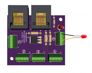
Satellite boards have a solder mask to label Satellite I/O pins. You can find Satellite I/O 5 by locating the circled number 5.
Each Satellite I/O has a 4 pin configuration. Review the pin configuration chart:
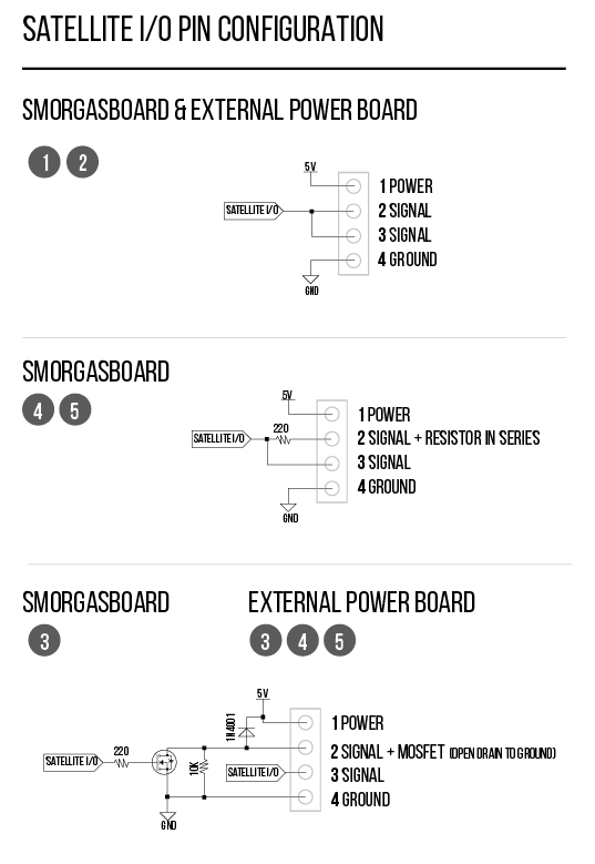
This tutorial uses a Smorgasboard Satellite. Satellite I/O 5 has the following pin configuration (from the left of the screw terminal block):
1 – Power
2 – Signal pin with resistor in series
3 – Direct signal pin
4 – Ground
Museduino boards were designed for robust rapid-prototyping. By including a resistor in series in the pin configuration, this minimizes the need for additional parts, breadboards or soldering.
Simply, connect the positive side (anode) of the LED to the screw terminal pin 2 (signal + resistor in series) and the negative side of the led (cathode) to screw terminal pin 4 (ground). You will need a screwdriver to tighten/loosen the screw terminals.
Then, connect the Smorgasboard satellite to Port A on the Museduino Shield via CAT5 cable.
Code
Copy code below or download from Github.
Upload the sketch to your microcontroller. You should have a blinking LED.
/*
  Museduino | LED Tutorial
  Turns on LED for one second, then off for one second, repeatedly.
*/

// Digital Pin 6 on Satellite Pin 5 via Port A
int s5A = 6;

// the setup routine runs once:
void setup() {
  // initialize the digital pin as an output
  pinMode(s5A, OUTPUT);
}

// the loop routine runs over and over again forever:
void loop() {
  digitalWrite(s5A, HIGH);   // turn the LED on (HIGH is the voltage level)
  delay(1000);               // wait for a second
  digitalWrite(s5A, LOW);    // turn the LED off by making the voltage LOW
  delay(1000);               // wait for a second
}
Want to add a button?