Cobalt Violet
Kisses yellow fiberglass
Copper is the art
Certified
Museduino 4.0 is certified as OSHWA-compliant open source hardware.

Schematics
Museduino Main Shield v4.0.2
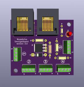
Museduino Smorgasboard v3.0
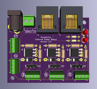
Museduino External Power v3.0
Museduino Port Extender v1.0.6
Features
Museduino Main Shield
Distributed I/O
The Museduino shield distributes 20 Arduino pins between 4 RJ-45 “ports”. A Satellite board connected on either port allows access to 5 specific Arduino pins to be used for sensors/actuators. The shield and satellite boards have a labeled solder mask to assist with configuration. Ports are labeled with a circled A, B, C, or D on the shield. The 5 Satellite I/O pins are labeled with a circled number 1-5 on the Satellite boards.
Use the following chart to decipher the Arduino pin distribution:
5V Power Jumper
The Museduino shield can power electronics separately from the Arduino by using the 5V Power Jumper. The jumper allows for choice in power supply: 5V from the Arduino or an external 5V.
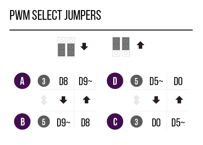
PWM Select
The Museduino allows distributed PWM pins to switch between ports. For example, pin D9~ on port B can switch places with pin D8 on port A. Pin D5~ on Port C can also switch with Pin D0 on port D. This feature is useful when you need an extra PWM pin to be accessed from a different port.
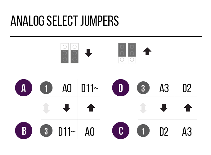
Analog Select
The Museduino also allows distributed Analog pins to switch between ports. For example, pin D11~ on port B can switch places with pin A0 on port A. Pin A3 on Port C can also switch with Pin D2 on port D. This feature is useful when you need an extra Analog pin to be accessed from a different port.
Satellite Boards
Since Satellite boards connected via CAT5 cables can be as long or short as needed, this ability is particularly useful for large-scale installations where distance between sensors/actuators is needed.
Each Satellite board is equipped with two RJ-45 connectors. This allows Satellite boards to be daisy chain-able for distance between sensors/actuators on the same port.
Each of the five Satellite 1/0 pins has a 4 pin configuration: 1 – power, 3 – Direct Signal, 4 – Ground. The 2nd configuration pin varies based on the Satellite board and your circuit needs.
See Satellite 1/0 Pin Configuration chart below:
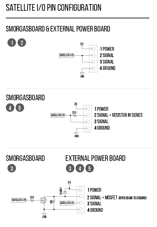
Museduino boards were designed for robust rapid-prototyping. Some Satellite 1/0 pin configurations include additional components to minimize the need for additional parts, breadboards or soldering.
Satellite 1/0 pins 1 and 2 on a Smorgasboard and External Power board are intended for use with Analog sensors. No extra components on the Satellite 1/0 pin configuration are included since resistor sizes vary depending on the analog input.
Satellite 1/0 Pins 4 and 5 on a Smorgasboard include a signal pin with a resistor in series.
Smorgasboard Satellite 1/0 pin 3 and External Power Satellite 1/0 pins 3, 4, 5 are intended for actuators that require higher power requirements. The optional configuration pin 2 includes a signal pin connected to a mosfet circuit. Follow the DC Motor tutorial for more details.
Smorgasboard Satellite Board
Named for its smorgasbord qualities, this satellite board allows for a wide range of sensor and actuator configurations on any port.
External Power Board
The External Power board is designed for actuators that require their own external power supply (NeoPixels, DC motors, Solenoids). Similar to the 5V Jumper, the onboard External Power Jumpers give you the option of Arduino 5V or External 6-12V.
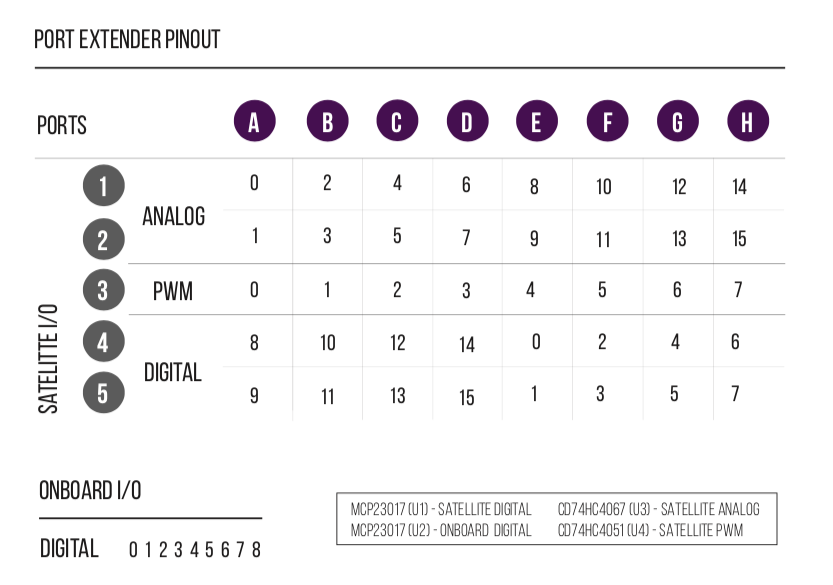
Port Extender board
The Port Extender board was designed for use with the dedicated i2c port, Port D on the Main Shield and intended for projects that need to control more input and output devices. The Port Extender is equipped with two MCP23017 i2c 16-bit i/o digital port expanders, a CD74HC4051 8-channel multiplexer, and a CD74HC4067 16-channel multiplexer.
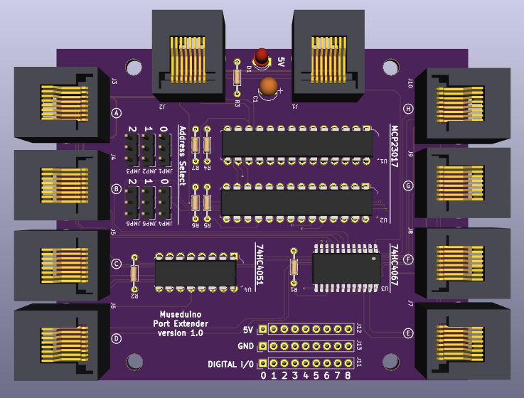
Along with the chips mentioned above, we use the Arduino’s dedicated i2c pins (A4, A5), an analog pin (A3), and a PWM pin (D5~) in order to extend the number of digital, analog, and PWM pins to be used with the Museduino system.
See Port Extender Tutorial for additional documentation.